

Thyristor
A thyristor is a solid-state semiconductor device with four layers of alternating N and P-type material.
![]()
Silicon controlled Rectifier(SCR)
• 3 terminal power semiconductor device
• Anode
• Cathode
• Gate
• Unidirectional device
• Current flows from cathode and anode only
• This current is controlled by Gate terminal.
• Used in switching ac power control
• High Speed switch
• Switches between conducting and non-conducting states instantaneously .
Construction
• Four layer and three junction device.
• Turned ON by applying small voltage to gate
• Gate Voltage controls the current from the device
Specifications
• Forward blocking voltage
• The value at which the SCR is in forward bias but not in conduction
• Forward break-over voltage
• The minimum forward voltage applied to gate to turn on SCR
• Peak reverse voltage
• Maximum reverse bias voltage applied to Gate
• Holding current
• Minimum current to keep the SCR in conducting state
• Latching current
• Minimum current to turn On the SCR
• Maximum ON state voltage
• Maximum voltage appears when SCR is conducting
• Current rating
• Ability of SCR to carry high magnitude current
• Maximum gate trigger current
• Maximum current that can be applied to Gate terminal
• Minimum gate trigger current
• Minimum current that can be applied to Gate terminal
• Gate power loss
• Power loss between gate and main terminal
• Turn ON time
• Tim required for reaching 90% of conducting state(2 to 4 µs)
• Turn OFF time
• Time required to switch OFF the SCR. (10 to 50 µs)
• Gate reverse voltage
• Maximum reverse voltage that can be applied to gate
Working
•
Two states of operation:
• ON State
• OFF State

ON State
• Gate is positive
• Forward biased
• The device turns ON
• After break-over voltage the SCR starts conducting.
• The minimum current required to turn on SCR is called latching current.
• The minimum current required to keep it in ON state is called holding current
OFF State
• Gate is open
• Reverse biased.
• A negligible leakage current flows in the circuit.
• If the value falls below holding current the SCR is turned OFF
Two transistor Model
• SCR has two transistors PNP and NPN connected adjacent in base.
• When positive GATE is applied:
• BE junction of Q2 is forward biased and transistor turns ON and generates collector current.
• Collector current turns Q1 ON.
• When both transistors saturate SCR is ON and remains in ON state even after removing GATE
![]()
V-I Characteristics:
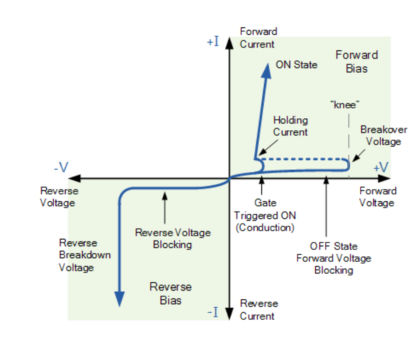
Vertical line- forward and reverse current in SCR
Horizontal line- forward and reverse voltage in SCR
It has 2 characteristics:
· Forward characteristics
· Reverse characteristics
Forward characteristics:
· When anode is positive with respect to cathode
· SCR does not conduct unless reaching the forward breakover voltage VBO .
· SCR remains in conducting state unless current falls below the holding current
· While SCR is not conducting a small leakage current flows through the device.
· When positive gate is applied the device starts conducting.
· The breakover voltage decreases with increase in gate current.
· At sufficiently large gate current SCR behaves like a pn junction rectifier.
· Device will be in low impedance state while conducting and high impedance state while not conducting
· The gate of the SCR controls the resistance between anode and cathode
Reverse characteristics:
· Anode is negative with respect to cathode.
· A leakage current of few microamperes flow through the device.
· Further increase in reverse voltage results in avalanche breakdown increasing the reverse current sharply.
Advantages
• Very small amount of Gate voltage
• Available with high current and high voltage ratings
Disadvantages
• Gate terminal has no control over scr after switch on.
• External circuits are required to turn OFF
• Operates only at low frequency of order 50-60hz
• Requires supplementary protection circuits.
Applications
• Power switching
• Phase control
• Choppers
• Battery chargers
• Inverter circuits


